We make preconfigured BeagleBoard with LinuxCNC drivers for your K40 Laser cutter. It's an easy fit in replacement for the MoshiDraw that comes Chinese factory installed. Our product doesn't require USB keys and works for Windows, Linux, Or Macs. It is a ready replacement so that you can use our mini 10"x5"x3" in your existing K40 laser cutter operation. No need for USB key nor the laser near your computer for driving LinuxCNC (ethernet cable is communication port), this board replaces all the MoshiDraw limitations. The laser driver also cuts in vectors (straight lines) not in pixels or dots as the standard Moshi driver utilizes. Just remotely login with a remote desktop or VNC software through your LAN to import machine code files.
In order to make this solution work you will need moderate to expert computer, electronic, and networking skills. Although novice users could install, we cannot recommend due to some lacking skills and knowledge that might be necessary. We try to make this installation as easy as possible with online instructions. After purchase we will need to know the subnet and static IP address you'd like your LinuxCNC beagleboard to interface. If none is provided the default product will ship preconfigured to 192.168.1.16. When on the same network subnet of your LAN you should be able to use any of several VNC desktop remote viewers to login. Login ships with default username and password both being "machinekit" without quotes.
Our LinuxCNC driver board also comes with the potentiometers preset with a nominal amount of stepper driver current. Not that adjustment should be necessary but we will show you how to further adjust the motor current if you desire in the instructions below.
Installation and Eula Terms of Agreement:
Warning these lasers represent a danger to inexperienced technicians or people with no skills, we assume no liability for either your laser hardware or personel/employee risk. Miles-Milling is void of liability for incorrect installation of part and by installing this replacement laser controller the technician is acknowledging his duty and liability to follow all the instructions in this manual. Miles-Milling.com also does not warrant either the contoller nor the hardware that is adjoined to the replacement, nor do we assume any responsibility to usage or personnel using this controller.
For further disclaimers please read the Eula, installation means acceptance of the terms and conditions.
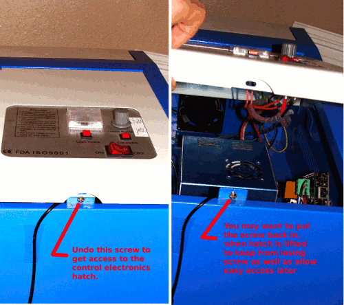
| Installation of this product is unbelievably easy. First make sure your Laser is powered down before doing any installation, if power is applied while installing it can damage your laser or controller!! We'll need access to the electronic compartment hatch of the K40 laser system. Before we can begin replacing the standard raster controller.
|
|
 |
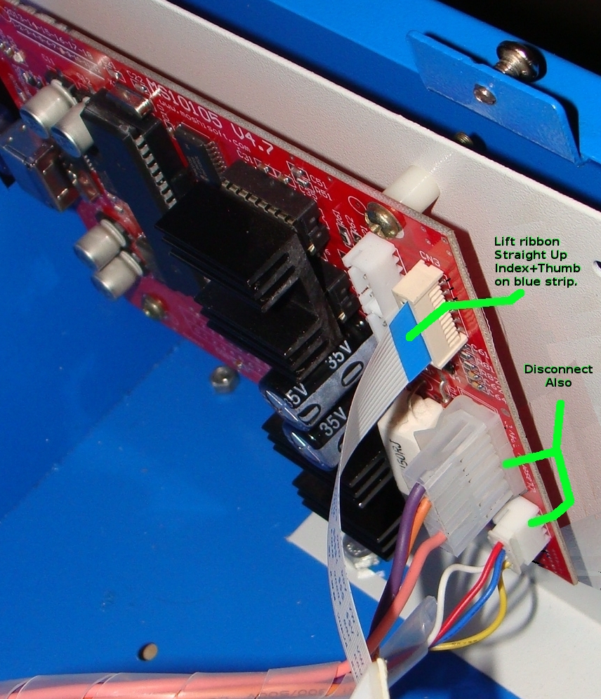
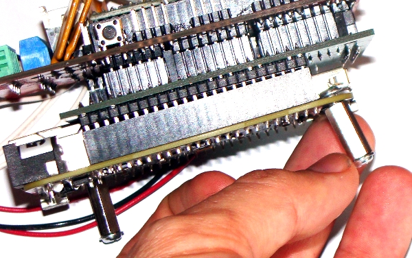
| You can choose to keep the MoshiDraw controller inside of the chassis, though I'm not sure why you'd want to do that if you want to only do vector laser cutting and by removing it we can use its prexisting sheet metal holes to insert the ethernet cable. If you keep the original MoshiDraw controller you'll need to drill a hole large enough through the side of the chassis to let in the network ethernet cable. Let's take a look at the chassis with the Moshi Draw board and the cables that must be disconnected to be reconnected to our board. Note to disconnect the ribbon cable just pull it straight up out of its connector on the MoshiDraw controller board, pull on the ribbon cable where the blue strip is located with index and thumb pinched over this area.
|
|
 |
| Next we start to reconnect various cables from the MoshiDraw controller to our LinuxCNC controller instead. We also need to add a Cat5 ethernet cable to the LAN port for communication to our LinuxCNC controller. Make sure the orientation of cables and polarity exactly match the picture below.
|
|
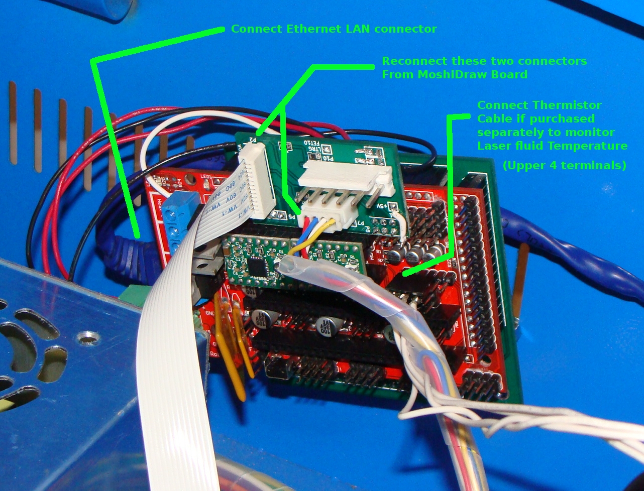 |
| Connect up the power cable to P10 as shown below, again make sure polarity is observed as shown below even though the connector is keyed.
|
|
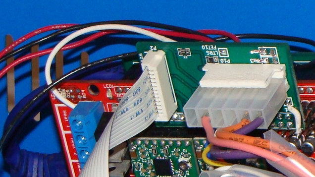 |
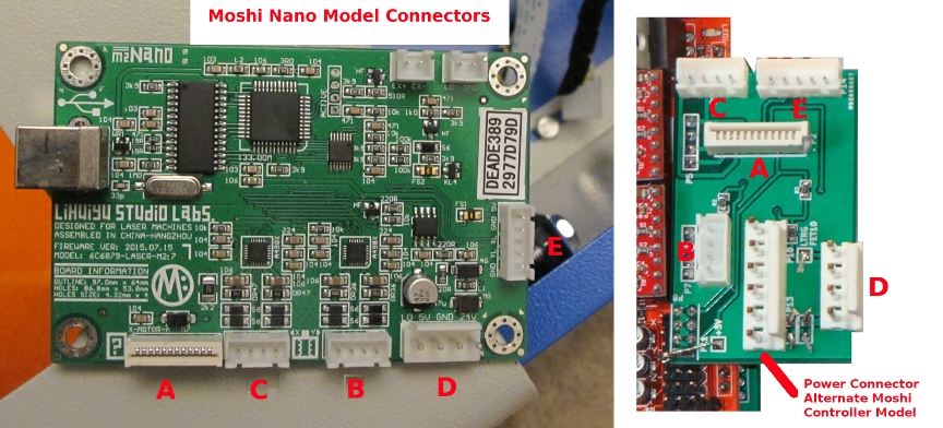
| We recently redesigned our connector board so that it could accept all old as well as new Moshi controller cables. Please see the following picture to see the compatible connectors. The old adapter connector as shown above has been obsoleted, but realize that even those old cables can now work on our more universal layout below:
|
|
 |
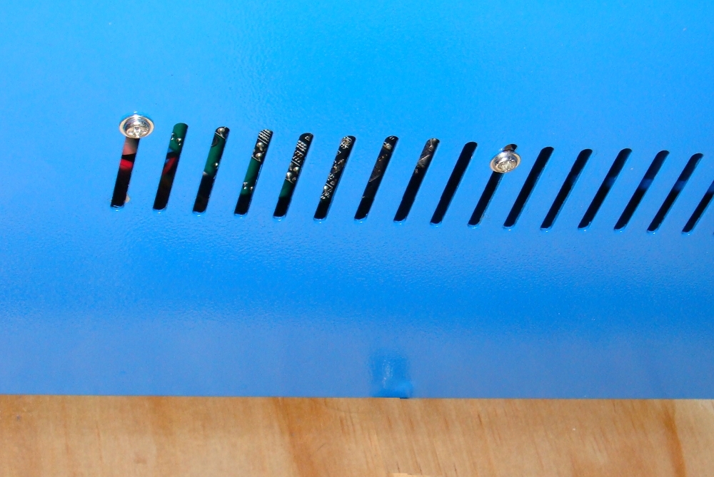
| We aren't responsible for proper mounting, and the following method has some risks as any other. You will be responsible for making sure that how you mount does not cause shorting on the Beagleboard. The product comes standard with two standoffs as shown below. Obviously the best way to mount would be to drill side holes in the laser chassis exactly matching the standoffs. Though of course one would have to be careful that none of the metal drilling shavings ended up shorting out the laser power supply or other electronics in the electronics bay. So for simplicity one can just slight loosen the screw between the top of the beagle and base standoff as shown below. Make sure again power is off to all electronics before doing this. Also inspect that by loosening the standoff it will not be able to touch any of the beaglebone components or solder pads. This little bit of lateral angle motion will allow us to easily screw from the other end of the venting holes.
|
|
 |
| With one of the beagleboard standoffs slightly lose as shown above, then use the bottom screw on the standoff to fasten to the venting holes. This angular degree of freedom will compensate for the distance between posts being different than available rungs of the vent holes. After getting mounted make sure you tighten all screws and standoffs as tight as can go so that it has no degree of motion or wobble left between the LinuxCNC beagleboard and the chassis.
|
|
 |
Usage and Troubleshooting:
Using your LinuxCNC Beagleboard plus stepper motor cape board stackup is as simple as plugging in the network cable. Turning on the power to the board stack, possibly needing to press a reset button on the motor driver board if their is a power on race problem. And logging into the VNC network with a remote desktop viewer. You can also move the files across from your local computer's hard drive files such a .ngc (gerber code) or .gcode to the beagleboard's folders by using a SSH (Secure Shell) client. These programs are readily available for free on gpl repositories. Your Desktop/Laptop OS will determine the correct binary download to obtain the free softwares to communicate with your beagleboard LinuxCNC OS, more on that later.
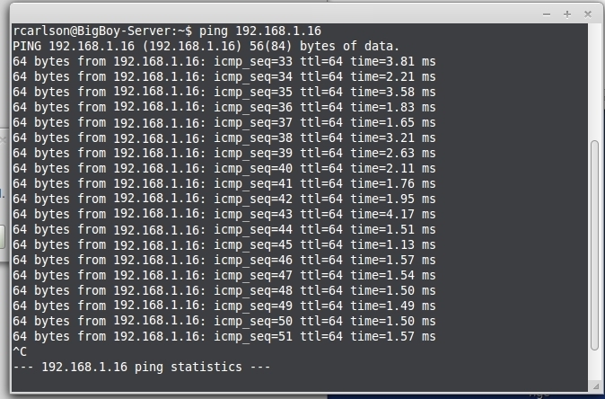
Before beginning on the communication and networking, we strongly recommend that you shut off your computer's firewall before trying any of the network commands below. A firewall blocking communication on a network is often times one of the biggest problems of failed networking and communications. By default the IP assigned to your beagleboard OS (Operating System) will be static address 192.168.1.16. This must match your local subnet and not conflict with another device/computer that might have the same static IP address. You can verify the correct subnet of your computer on a LAN ethernet by opening a command/terminal window. For linux/mac you would type "ifconfig -a" without the quotes and hit enter, for windows you would type "ipconfig /a". The results will show your computers
IP address such as 192.168.1.36 or say 10.0.0.18 or maybe 192.168.2.56. Your subnet for that lan connection would then be the first 3 numbers between the dots if the subnet mask was 255.255.255.0. Our first example 192.168.1.36 being reported back by ipconfig would have also be the same subnet 192.168.1.X where X is don't care and thus see our default beagleboard as being on the same local subnet which by default is 192.168.1.16. In either windows, mac, or linux you should then be able to type ping 192.168.16 from say your computer and a reply should come back with a ping of the beagleboard not timing out if it sees the board and is on the same subnet as the ethernet network. If you see your subnet is 10.0.0.X for example you need to tell us this so that we can personally configure your
beagleboard at configuration to say 10.0.0.15 instead. In fact we can set your beagleboard to any ip you wish to specify but please let us know when you buy it if you don't want the default subnet 192.168.1.X and fixed address of 192.168.1.16.
Software:
You actually need two packages of software to communicate with your LinuxCNC beagleboard over the ethernet. One you need a VNC remote desktop viewer, I use the gpl free vinagre in linux mint. The remote desktop viewer will give you a window/viewer as if the Beagleboard remote operating system had a hardware monitor piped into your PC/laptop. Your PC/laptop acting as a dummy terminal/display for the remote LinuxCNC beagleboard. In other words you will be remotely connected on your desktop/laptop with a VNC connection to see an X window (virtual monitor) of the LinuxCNC server. Anyone who has used a virtual host or X window to another operating system will get the drift of what we are trying to say here on being remotely logged on and viewing another computer (in this case the beagleboard)
through the ethernet. The second piece of software that will be required to move data files to and from your
remotely connected LinuxCNC beagleboard will be a SSH (secure shell) client. In linux and these case examples I use the SSH client present in nemo/nautilus of my Linux Mint Desktop computer, which allows a file system very similar to the host directory file system . There are also standalone SSH clients like Putty, as well as Vinagre also supporting ssh servers. At the end of my elaboration I will try to give sources on the internet where you can download various SSH clients and compatible remote desktop viewers for Macs, Windows, and Linux.
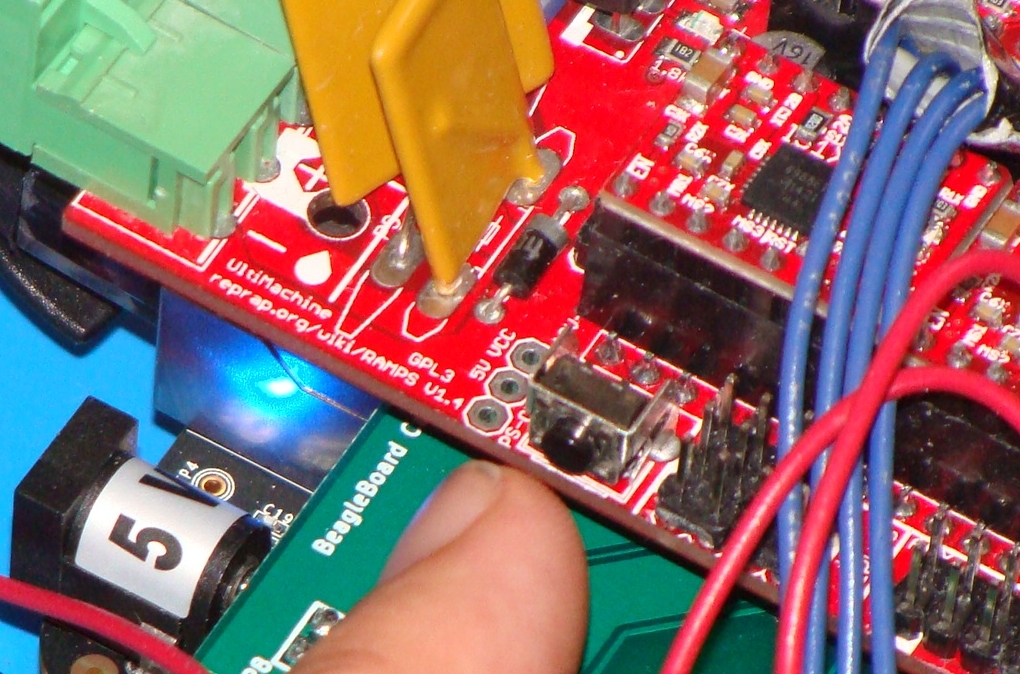
| Let's start with my case example of my work ethernet. The IP address of the LinuxCNC driver is at the default 192.168.1.16 and the work network has a router at local ip address 192.168.1.1 with a subnet 192.168.1.X and subnet mask obviously at 255.255.255.0. The first operation is to connect the device into the ethernet through a patch cable. Power on the milling/LinuxCNC controller box. Do a warm reset after power comes up by pressing the reset button on the driver board as shown below:
|
|
 |
| Then open up a command/terminal and ping 192.168.1.16, until the ping shows a reply. If there is no reply then your computer is not seeing the beagleboard.
|
|
 |
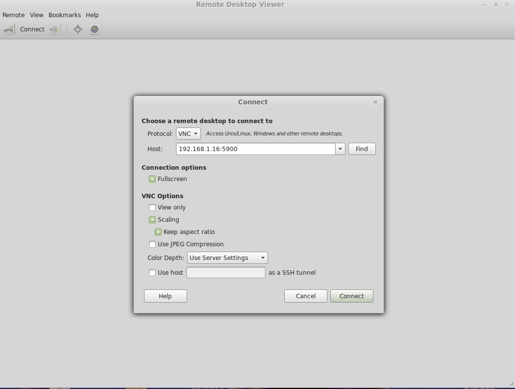
| The first time we start vinagre/VNCviewer we need to specify VNC as the desktop viewer type, we also need to enter the IP address as shown below. If its the first time to start a connection to the LinuxCNC beagleboard your viewer might ask for a username and password. Use both "machinekit" without quotes for any username or password prompt.
|
|
 |
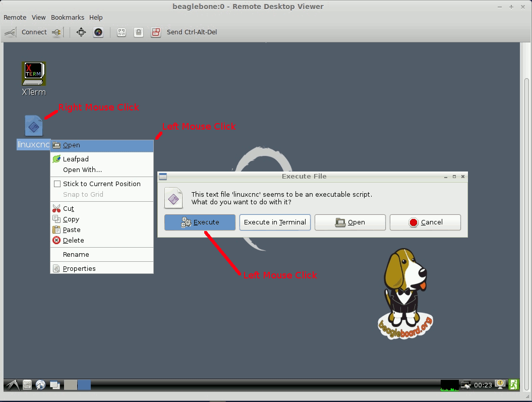
| Start the Linux CNC application.
|
|
 |
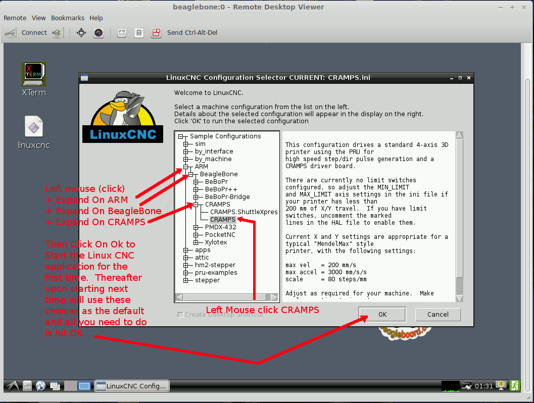
| We need to choose CRAMPS if its the first time we started LinuxCNC application, thereafter just click on OK.
|
|
 |
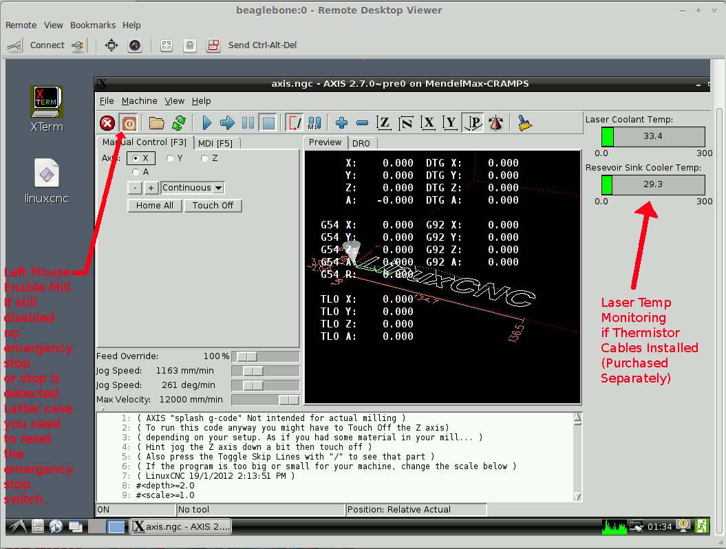
| After clicking OK wait about 1 minute for the linuxCNC package to start. At this point you will see the main application. You'll want to Enable the Mill as shown in the photo below. And also you'll need to do a "Home All" for the laser to find it's zero position.
|
|
 |
| To open CAM files for milling obviously we need to take the exported .ngc/gcode file and move it from our PC/laptop to the beagleboard Ubuntu OS file system. Then Open with the File->Open menu system of axis LinuxCNC application. To move the files over from the remote computer to the LinuxCNC host we will use SSH. This example uses nemo/nautilus in Linux Mint/Ubuntu however free software for Linux/Mac/Windows, such as Putty can also be used to SSH.
|
|
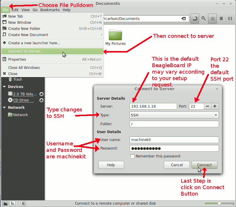 |
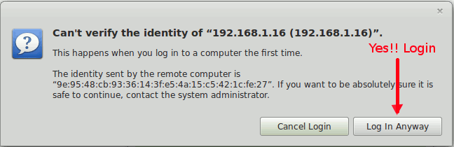
| First time login will require that you verify the certificate by login anyway.
|
|
 |
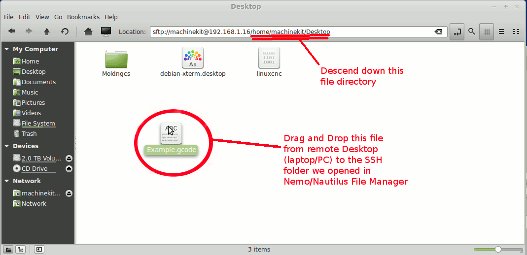
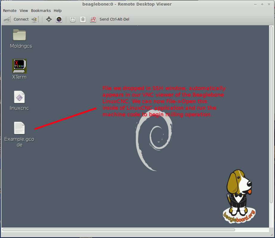
| Afterwards we can just copy and paste or move the CAM files as shown below by dragging and dropping into the nautilus/nemo file system application folder. Notice we first descended down the folder hierachy of /home/macinekit/Desktop, you can place your machine files anywhere but we do this for convenience as the VNC window will automatically show the file show up on Desktop after the file is moved with the SSH transfer.
|
|
 |
| The VNC viewer shows the SSH file copied onto the Beaglebone Desktop.
|
|
 |
A list of other SSH packages and VNC free viewers for Windows, Mac and Linux are provided below:
| Linux (As shown in these examples): |
|
Free SSH Use the standard Nemo/Nautilus File Manager, Already part of GNOME, Non GNOME base Linux use FOSS/linux community to determine best alternate solution |
|
Free VNC software for Linux. Many great choices available to FOSS, but we have had good results with Vinagre which is what is used in this manual. Also TightVNC is hardware/OS indifferent platform. |
|
| MAC (As shown in these examples): |
|
Typical Application and Tutorial and Work Flows
In order for the laser to cut (turn on) with the BeagleBoard MoshiDraw replacement three conditions must be met. One the hardware "Laser Switch" must be enabled or pressed down. Also on the software side LinuxCNC must have the laser mill enabled with the mouse selection. And finally the laser to be modulated will occur whenever the .gcode/ngc states a mill < 0 in depth position. Whenever the mill gcode call for a z position that is greater than zero the laser will shut off. The last statement is the one we need to know to manufacture gcode files. We'll cover how to generate .gcode/.ngc files using both free software gpl workflows, and then just briefly mention an alternate .gcode generator for the laser cutter using proprietary software CamBam.
The workflow to obtain a CAM machine code .gcode/.ngc file to drive the linuxCNC laser cutting application is to generate a vector file such as a .dxf or .svg based on a mechanical CAD package or graphics editor to vector software package. With these vector files (.dxf/.svg) the next step is to convert with another application into a CAM (.gcode/.ngc). Obviously we need the cutting vectors where the laser is to cut in lines to sit below z=0 (negative z cutting depth/position) in order for the laser to to turn on and meet the conditions of the previous paragraph.
One free gpl CAD software that can be used to generate very good 2-D mechanical drawings is libreCAD. Beings it reminds me of the older AutoCAD packages where simple 2-D designs can quickly be fabricated this is my primary way of generating vector files. You can even import graphics files such as .gif and .jpg as a background image. Then use these to trace over lines by hand with your mouse inside the set spacings of snaps and grids. Or just simply start with a 2-D design from scratch and use position coordinates or relative commands to draw shapes and lines. Once a sufficient 2-D CAD drawing of your cutting lines is obtained, just export and save these as type .svg or .dxf (depending on CAM package you use). Of course pay for proprietary packages can also be used to do the same thing
Another way to generate a vector file from say a .gif/.jpg image file is to use a free gpl package called Inkscape. Here you can have it trace an outline (best to see youtube videos) to convert raster point pixels in a gif/jpeg/bmp into vector cut lines. Then once again export the vector files as a .svg or .dxf file to be used in your CAM package.
Assuming that you use a CAD package or Inkscape to generate a vector file (.svf/.dxf) we now need to convert this vector file into a CAM (.gcode/.ngc) format. A free gpl software to do this is Pycam, we will actually show in detail how to use Pycam to do this job next. Another proprietary solution is to obtain a temporary license (limited time usage) or pay $150 dollars for a licensed copy using say CAMBAM. There are also other solutions for CAM packages, but for brevity I'll restrict the CAM file generation to these two options. Pycam will only accept vector file .svg, and I believe that CAMBAM will only use .dxf vector file imports.
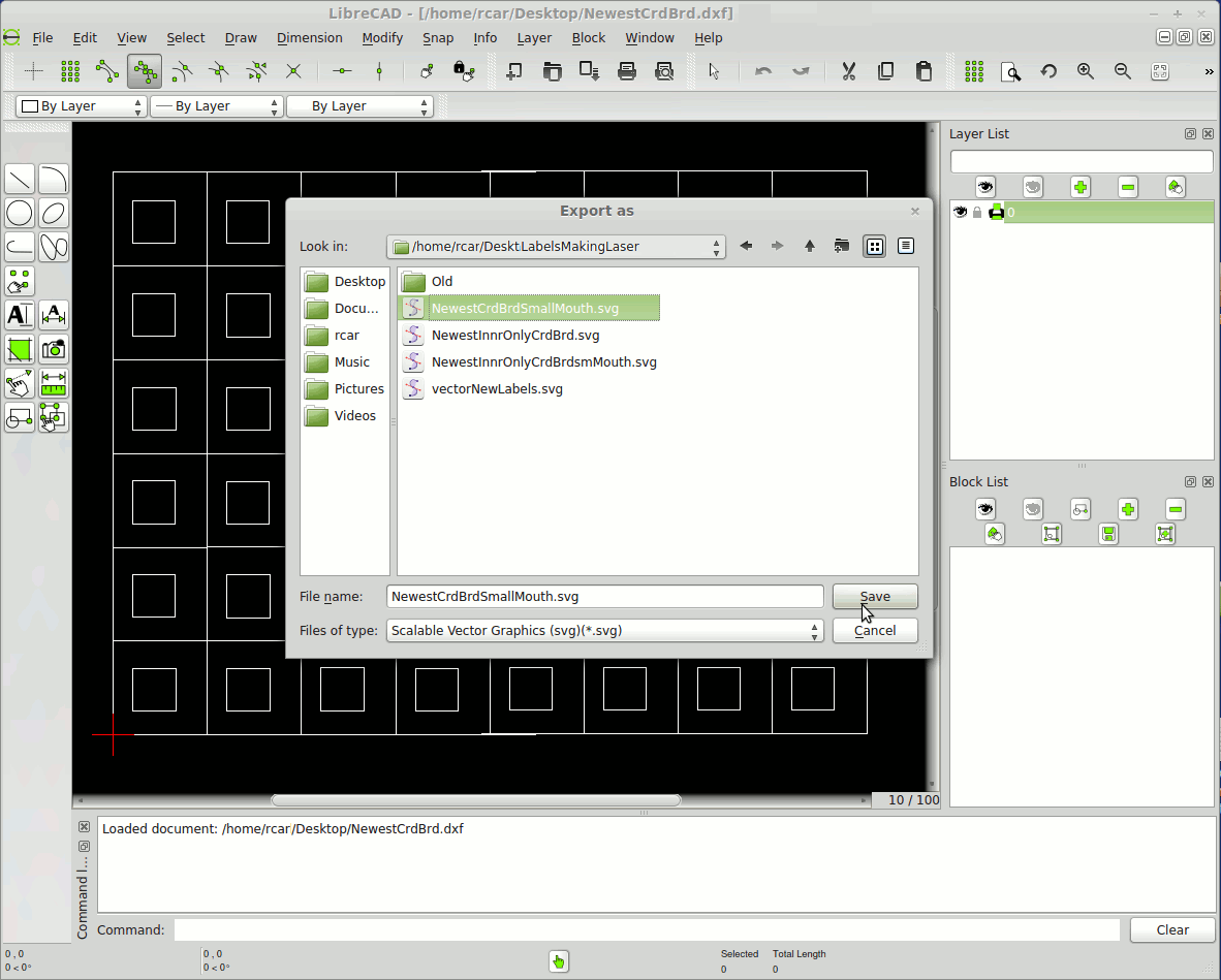
| Assuming we use a CAM package of the free gpl Pycam, to convert our .svg vector file let's start with our free 2-D libreCAD package of typical cut we want to make where the lines exist as showing the laser cutting. In the picture below is a snapshot of the libreCAD package where we exporting to .svg format to be used by free gpl Pycam application next.
|
|
 |
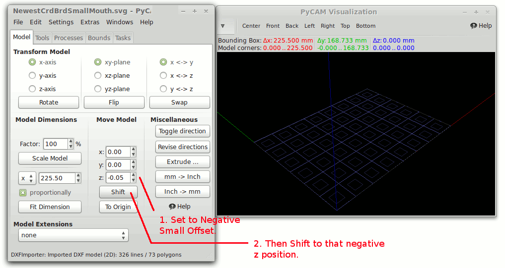
| Next we need to File-> Open Model and browse to our .svg we exported in previous paragraph. We will need to shift this below the z access for the laser to cut (turn on), so you use a small -.05 offset and click the shift button. You want to make this offset small and not larger because linuxCNC uses a maximum and finite (though larger) slew rate to simulate a falling conventional mill. The smaller the offset the quicker turn on followed by cutting action as the laser moves on the x-y plain, negative .05 works well.
|
|
 |
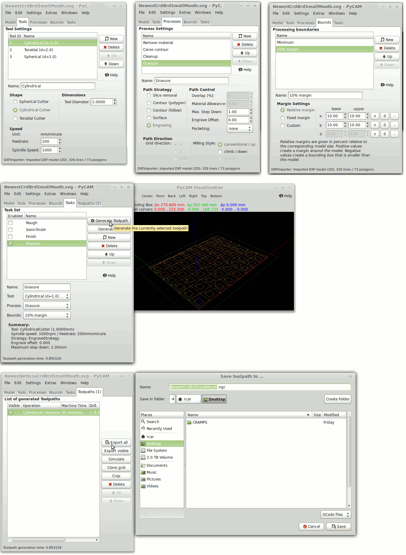
| The following snapshots are showing all the various tabs tools, processes, boundaries, and tasks to complete and generate a CAM .ngc/.gcode file that can be SSH transfered onto your beagleboard to run a LinuxCNC cutting.
|
|
 |
As far as using CAMBAM a proprietary package instead of the free Pycam application. You would export from libreCAD a .dxf file. Then the best way to see how to generate a CAM file is by following the youtube video below, but remember after importing the flat .dxf that you place the traces below the z=0 axis so that the laser can be turned on when the mill drops below to negative:
CAMBAM video for generating Laser CAM .ngc/.gcode file
We only had time to show two simple and easy to use applications to generate very good vector to CAM files to drive your new Laser cutter using your replaced LinuxCNC application and controller. However, you can use innumerable package to do the same thing and youtube videos can explain very well how to implement the workflow that works best for you. Remember LinuxCNC sets the standard for true vector cutting, MoshiDraw cannot even come close to this as it does only rasters scans and not true vector or line cuts.
Conclusive Information about this Product
This product comes ready to install and replace the standard MoshiDraw driver in the K40 Chinese Laser Cutter. This product removes many of the restrictions of the MoshiDraw Software, in particular the requirement for a USB dongle, or a PC with a USB in vicinity as all communication with the BeagleBoard is through an ethernet connection. So you can remotely place your laser cutter away from your desktop or workstation where files for cutting are downloaded. Also this solution allow true vector or line cutting, unlike the standard Moshi Solution that only allow raster or dot/point scanning, this is absolutely for accurate and real laser cutting. We also provide dual hermetically sealed thermistor cables if you wish to have LinuxCNC display liquid cooling temperatures in degrees Celsius, which I believe MoshiDraw does not allow remote monitoring of coolant temperature. Installation is an easy cable swap. It's entirely OS (operating system) platform independent, as the host beaglebone acts as a minicomputer with its own local OS and linuxCNC application. The entire firmware is OpenSource and provided online as CRAMPS images and source. Further details of locations of these sources we used to make this product will be provided upon request if desired. Thank you all of the opensource community for this extremely economical and excellent product.